TraceBox

// The easy way of validating motor control software.


TraceBox


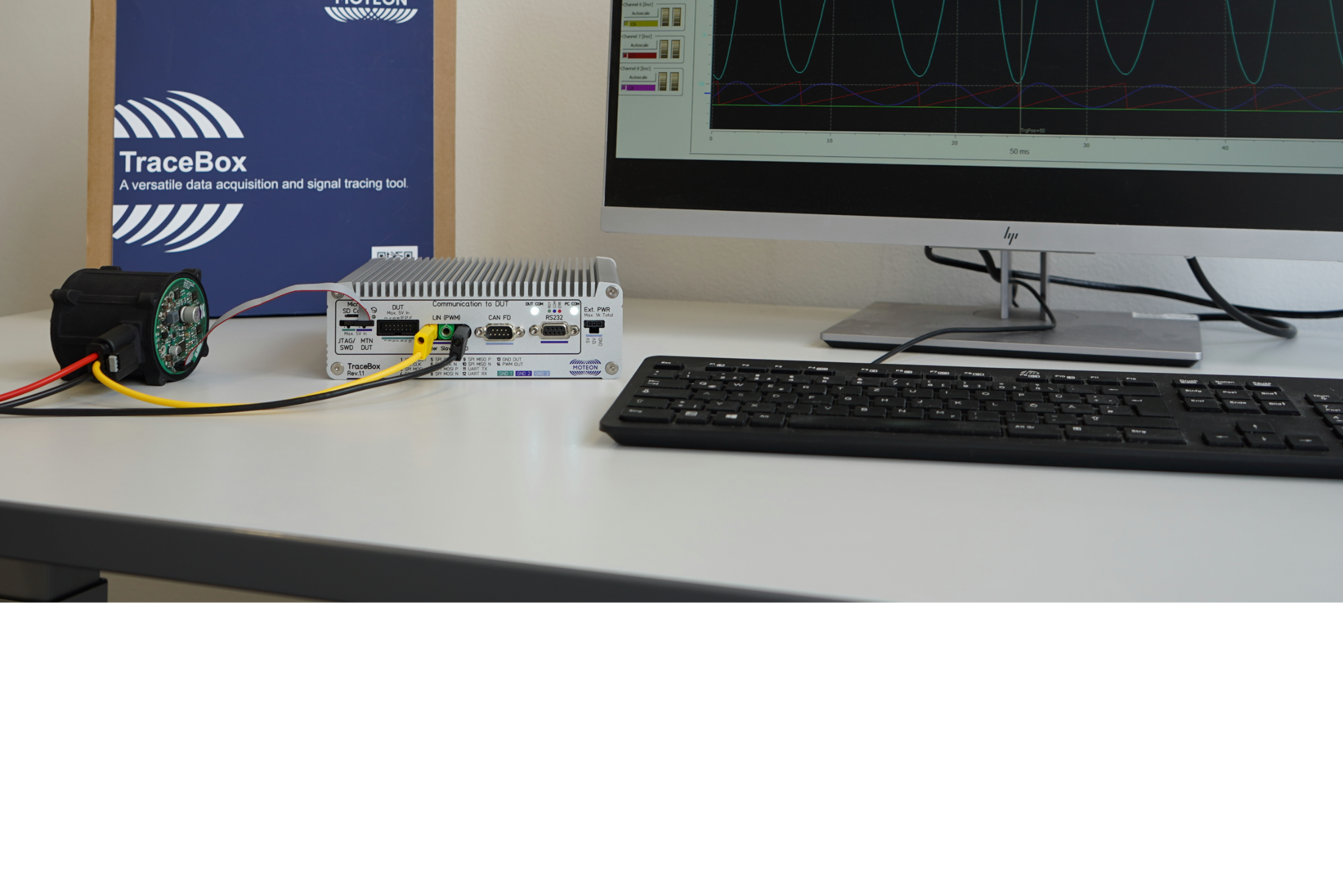
In the early phase of software development, tests on real hardware can reveal unexpected errors. However, due to the high setup effort, in most cases the software is only tested with simulators. The TraceBox is a versatile data acquisition and communication tool for the development and validation of motor control software that can be used in conjunction with real target hardware. The TraceBox is connected between the customer application and the PC and establishes the required interface via plug & play and controls the device with the user-friendly PC tools.


Buy online Documents


View the latest Videos and get to know the MOTEON TraceBox in more detail

View the TraceBox on YouTube View the latest webinar

Your benefits at a glance


TraceBox as an interface between hard- & software


A major benefit of the TraceBox is the high variable connectivity in use as a standalone device as part of a desktop developer setup or in a test bench environment. This offers many possibilities that impact the development process and the product life cycle.

// Identification of issues throughout the entire development phase

The early identification of issues is crucial to reduce development costs and maintain the project schedule. The TraceBox is a tool to identify issues with minimal effort. Flash and debug your motor control software with the integrated XMCTM Link without disconnecting and re-connecting the device under test (DUT).

// Verification of MCTRL algorithms & signal analysis

Data streaming via SPI/UART optimized for low cost microcontrollers enables you to verify your motor control algorithms by tracing the microcontroller internal data while the motor is running.

// Validation of software adaptions in the ongoing development process

Software validation is a complex procedure that can be time-consuming due to the various settings of your motor control software. The TraceBox allows an in-depth analysis of the functionality of software adjustments. Change your motor control parameters and validate the system behavior in real time. No re-flashing required.

// Direct implementation in the installed, application-oriented state

Based on the high connectivity and plug & play principle, the TraceBox can be used as a standalone device as part of a desktop developer setup as well as embedded in a test bench environment.

One TraceBox for various use cases

  • In-depth analysis of the functionality of software adjustments
  • No disconnecting and re-connection the device under test
  • Standalone device as part of an on-desk developer setup
  • Embedded device in a test bench environment
  • Individual tools for efficient identification of errors in the early developing phase


The TraceBox in various scenarios

Standalone device


  • Fix test and development setup
  • Efficient identification of software errors and system behavior
  • Evaluation rotor position estimator
  • Setup and verification position sensor
  • Timing measurement, state change monitoring


Embedded device


  • Integration in test bench concepts
  • Software development and debugging
  • Identification and analysis of software bugs and system behavior
  • Timing measurement, state change monitoring
  • Synchronization of several development setup members


Read more

One TraceBox with impressive connectivity

  • High level communication and MCTRL real time data tracing
  • Data streaming via SPI/UART optimized for low cost microcontroller
  • Target communication with various application protocols and interfaces (LIN, CAN FD, RS232)
  • Flashing and debugging via SWD (XMCTM Link functionality)
  • Time synchronization via EtherCAT in embedded test environments

View Block Diagram

Your selection of interfaces


The interfaces allows the TraceBox flexible deployment options and enables all the features of modern and customized motor control software development. To protect internal microcontrollers a grounding concept isolates certain interfaces of the TraceBox.

DUT Interfaces


  • JTAG/SWD interface according to the XMC™ Link interface
  • Isolated SPI, UART or PWM connection with pre-assembled ribbon cable


The TraceBox provides small connectors with various interfaces towards the DUT electronics. The pin mapping of the JTAG/SWD interface is created according to the XMC™ Link interface. Alternatively, the SWD pins of the JTAG/SWD connector are available on the MTN DUT connector. With the pre-assembled ribbon cable, it is also possible to easily realize isolated SPI, UART or PWM connection. In case of using the SPI interface, the TraceBox acts as a slave. Due to small space requirement and different design variants, the connector is also recommended for use on the DUT electronics. The TraceBox provides a common 2.54 mm pitch connector with isolated single-ended or differential SPI and UART interface.

LIN


  • Efficient master-slave network
  • Maximum data rate of 19.2 kbps
  • Robust and high noise immunity
  • Stable data transmission


LIN enables efficient communication between the TraceBox and the DUT. The LIN interface of the TraceBox is compliant to LIN specification 2.2A with a maximum data rate of 19.2 kbps. Due to the characteristics of LIN it allows a robust and high noise immunity for a stable data transmission.

CAN FD

(Coming Soon)


Parametrics


Housing material

Extruded aluminium A6063S-T5, silver

Dimension

61.5 x 186.5 x 177.0 mm (1.8 kg)

Power Supply Interfaces

Lab/banana sockets: Deltron 571-0x00
DC jack: Würth Elektronik 694108105102

Supply voltage via Lab/banana sockets

12 VDC ... 60 VDC (Max. 5 A)

Supply voltage via DC jack

12 VDC ... 24 VDC (Max. 5 A)

Operating temperature

15 ... 40 °C

Order

Order online

Buy online via Hitex GmbH

Scope of delivery

TraceBox, AC/DC power adapter, ribbon cables

Product status

TraceBox Rev.1.1

Updates

Firmware update with feature extension of the first-generation TraceBox

Packaging size

250 x 250 x 80 mm (2.5 kg)

Documents

Product Brief
Quick Start Guide

1.   Download and install the latest TraceBox firmware.

2.   Set up the power supply for your TraceBox.

3.   Connect the TraceBox with your PC using Ethernet.

4.   Connect the TraceBox with the device under test via your preferred interface.

5.   Use the PC tools to get started.


For more documents goto Infineon Developer Center

Infineon Developer Center

Product Information